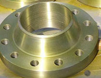
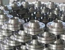
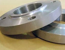
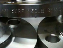
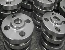
ASTM A182 Low Alloy Steel flanges Alloy Steel Flanges are made in different steel alloys. The flanges vary in dimensions and types. There are ½ inches through 48 inches of nominal diameter sizes of flanges. Navstar Steel is a leading manufacturer of the ASTM A182 Low Alloy Steel flanges as well as the other types of alloys. The ASTM A 182 specification specifies flanges for high pressure services.
Alloy steel flanges are fittings used to connect or terminate pipes, valves, or equipment within piping systems that operate under demanding conditions, such as high-pressure or high-temperature environments. These flanges are constructed using various grades of alloy steel, which contain additional elements beyond carbon and iron to enhance specific properties required for particular applications.

| Standard | Class | Diameter | Bolt Circle Diameter | Number of Bolts | Bolt Size | Diameter of Bolt Hole |
|---|---|---|---|---|---|---|
| AS4087 Flanges | PN14 Flanges | 95 | 67 | 4 | M12 | 14 |
| AS 2129 Flange | Table C Flanges | 95 | 67 | 4 | 13 | 14 |
| Table D Flanges | 95 | 67 | 4 | 13 | 14 | |
| Table E Flanges | 95 | 67 | 4 | 13 | 14 | |
| Table F Flanges | 95 | 67 | 4 | 13 | 14 | |
| Table H Flanges | 114 | 83 | 4 | 16 | 17 | |
| Table J Flanges | 114 | 83 | 4 | 16 | 17 | |
| ANSI B16.5 Flanges | ANSI 150 Flanges | 89 | 60 | 4 | 13 | 16 |
| ANSI 300 Flanges | 95 | 67 | 4 | 13 | 16 | |
| ANSI 600 Flanges | 95 | 67 | 4 | 13 | 16 | |
| ANSI 900 Flanges | 121 | 83 | 4 | 19 | 22 | |
| ANSI 1500 Flanges | 121 | 83 | 4 | 19 | 22 | |
| ISO 7005 (DIN) Flange | PN6 Flange | 80 | 55 | 4 | M10 | 11 |
| PN10 Flange | 95 | 65 | 4 | M12 | 14 | |
| PN16 Flange | 95 | 65 | 4 | M12 | 14 | |
| PN20 Flange | 90 | 60.5 | 4 | M14 | 16 | |
| PN25 Flange | 95 | 65 | 4 | M12 | 14 | |
| PN40 Flanges | 95 | 65 | 4 | M12 | 14 |
| Grade | C | Mn | Si | P | S | Cr | Mo |
|---|---|---|---|---|---|---|---|
| F1 | 0.15 max | 0.3-0.6 | 0.5 | 0.03 | 0.03 | 4-6 | 0.44-0.65 |
| F5 | 0.15 max | 0.3-0.6 | 0.5-1.0 | 0.03 | 0.03 | 4-6 | 0.44-0.65 |
| F9 | 0.15 max | 0.3-0.6 | 0.5-1.0 | 0.03 | 0.03 | 8-10 | 0.9-1.1 |
| F11 | 0.5-0.15 | 0.3-0.6 | 0.5-1.0 | 0.03 | 0.03 | 1.0-1.5 | 0.44-0.65 |
| F12 | 0.15 max | 0.3-0.6 | 0.5 | 0.03 | 0.03 | 4-6 | 0.44-0.65 |
| F22 | 0.50.15 max | 0.3-0.6 | 0.5 | 0.03 | 0.03 | 4-6 | 0.44-0.65 |
| F91 | 0.15 max | 0.3-0.6 | 0.5-1.0 | 0.03 | 0.03 | 8-10 | 0.9-1.1 |
| Grade | Tensile Strength | Yield Strength (0.2%Offset) | Elongation |
|---|---|---|---|
| F1 | 275 | 485 | 20 % |
| F5 | 275 | 485 | 20 % |
| F9 | 380 | 585 | 20 % |
| F11 | 205 | 415 | 20 % |
| F12 | 275 | 485 | 20 % |
| F22 | 205 | 415 | 20 % |
| F91 | 380 | 585 | 20 % |




| ASTM Specification | ASTM A182 , ASME SA182 |
|---|---|
| Size in inch | 1/2 inch (15 NB) to 48 inch (1200NB) |
| Standards |
ANSI/ASME B16.5, B16.48, B 16.47 Series A & B, EN-1092, BS4504, BS 10, DIN |
| Class and Pressure Chart | 150#, 300#, 600#, 900#, 1500#, 2500#, PN6, PN10, PN16, PN25, PN40, PN64 etc. |
| ANSI/ASME B16.34 | ANSI PRESSURE RATING | ||||||
|---|---|---|---|---|---|---|---|
| Temperature °F | 150# | 300# | 400# | 600# | 900# | 1500# | 2500# |
| -20 to 100 | 265 | 695 | 925 | 1390 | 2085 | 3470 | 5785 |
| 200 | 260 | 680 | 905 | 1360 | 2035 | 3395 | 5660 |
| 300 | 230 | 655 | 870 | 1305 | 1955 | 3260 | 5435 |
| 400 | 200 | 640 | 855 | 1280 | 1920 | 3200 | 5330 |
| 500 | 170 | 620 | 830 | 1245 | 1865 | 3105 | 5180 |
| 600 | 140 | 605 | 805 | 1210 | 1815 | 3025 | 5040 |
| 650 | 125 | 590 | 785 | 1175 | 1765 | 2940 | 4905 |
| 700 | 110 | 570 | 755 | 1135 | 1705 | 2840 | 4730 |
| 750 | 95 | 530 | 710 | 1065 | 1595 | 2660 | 4430 |
| 800 | 80 | 510 | 675 | 1015 | 1525 | 2540 | 4230 |
| 850 | 65 | 485 | 650 | 975 | 1460 | 2435 | 4060 |
| 900 | 50 | 450 | 600 | 900 | 1350 | 2245 | 3745 |
| 950 | 35 | 280 | 375 | 560 | 845 | 1405 | 2345 |
| 1000 | 20 | 165 | 220 | 330 | 495 | 825 | 1370 |
| AMERICAN SOCIETY OF MECHANICAL ENGINEERS (ASME) |
|
|---|