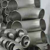
Pipe Fittings Chrome Alloy 90° Elbow An ASME B16.9 90 Deg Elbow is also known as a 90 bend, 90 ell or quarter bend. A 90 Deg Elbow is easily attached materials like to copper, plastic, cast iron, steel, and lead, and is attached to rubber with the help of stainless-steel clamps. Other materials the ASME B16.9 90 Deg Elbow is available in include silicone, rubber compounds, galvanized steel, and nylon. Typically in a piping system, the pipes or tubes are attached to the fittings constructed of similar material. For instance if the pipe used is of a stainless steel variety, the corresponding ASME B16.9 elbow 90 degree will be attached with the same stainless steel grade. A 90 Degree Mitered Elbow is primarily used to connect hoses to water pumps, valves and deck drains.
A chrome alloy 90° elbow is a type of pipe fitting specifically made from chromium alloy steel, designed to facilitate a directional change of the pipeline by a 90-degree bend while offering the enhanced properties of chrome alloys.
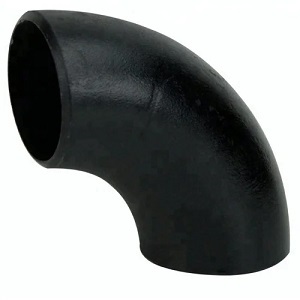
Steel Buttwelding Pipe Fittings such as 90 Degree Elbow and Bends are meant for use in applications with Full service Pressure. The standard for DIN 2605 90 Deg Elbow Type 3 specifies that the design as well as the dimensions of seamless and welded steel SCH 80 90 Degree Elbow and bends rated for the same internal pressure as the pipes to which the Buttweld Elbow 90 Degree has to be to connected.
Different types of 90 Deg Elbow Long Radius available in the market are - ERW, Seamless, Welded as well as Fabricated Pipe Fittings. The Manufacturing process of ASME B16.9 Elbow 90 Deg includes steps like - Pushing, Pressing, Forging, Casting, etc. Key markets and industries for Alloy 625 90 Deg Elbow Short Radius are as follows - Bitumen upgraders, Nuclear power (mostly seamless), Heavy oil refineries, Petrochemicals and acids.
| Specifications | ASME B16.9 90 Deg Elbow |
|---|---|
| ASME B16.9 90 Deg Elbow size | Seamless Butt Weld Fittings: 1/2″ – 10″ Welded Butt Weld Fittings: 1/2″ – 48″ |
| 90 Deg ElbowDimensions | ASME/ANSI B16.9, ASME B16.28, MSS-SP-43, BS4504, BS4504, BS1560, BS10 |
| 90 Deg Elbow Short Radius Thickness | SCH10, schedule 20, schedule 30, STD schedule 40, schedule 60, XS, schedule 80, schedule 100, schedule 120, schedule 140, schedule 160, XXS available with NACE MR 01-75 |
| 90 Deg Elbow Lr Types | Seamless / ERW / Welded / Fabricated Pipe Fittings |
| 90 Deg Elbow Long RadiusType | DN15-DN1200 |
| Connection For Carbon Steel 90 Degree Elbow Fitting | Welding |
| 90 Degree Pipe Elbow Bending Radius | R=1D, 2D, 3D, 5D, 6D, 8D, 10D or Custom Pipe Fittings |
| ASME B16.9 90 Deg Elbow Size Range | ½” NB to 24″ NB in Sch 10s, 40s, 80s, 160s, XXS. (DN6~DN100) |
| 90 Deg Street Elbow Fittings | Angle : 22.5 deg, 30deg, 45 deg, 90 deg, 180 deg, 1.0D, 1.5D, 2.0D, 2.5D, 3D, 4D, 5D,
6D, 7D-40D. Standard: ASME B16.9, ASME B16.28, ASME B16.25, MSS SP-75 DIN2605 JISB2311 JISB2312 JISB2313, BS, GB, ISO |
| Manufacturing process of 90 Deg Short Radius Elbows | Push, Press, forge, Cast, etc. |
| Stainless Steel 90 Degree Compression Elbows Test Certificates | EN 10204/3.1B Raw Materials Certificate 100% Radiography Test Report Third Party Inspection Report, etc |
| Origin & Mills For ASME B16.9 Elbows 90 Deg | Japanese, Indian, USA, Korean, European, Ukraine, Russian |
| Key markets and industries for Elbows 90 Sch 10 |
|
| Application of Elbows 90 Sch 80 |
|
| Material Test Certificates (MTC) as per EN 10204 3.1 and EN 10204 3.2, Test Certificates certifying NACE MR0103, NACE MR0175 | |

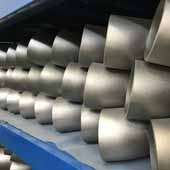

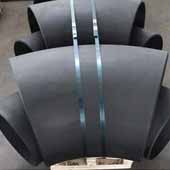


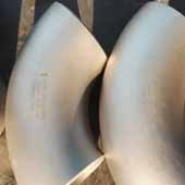



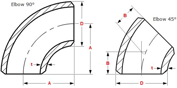
| ASME B16.9 90 Degree Elbow dimensions | ||||||
| inches | ND | mm | Center to center | Radius | Center to end | Back to face |
| D | O | A | B | K | ||
| 1/2 | 15 | 21,34 | 76,20 | 38,10 | 15,87 | 47,62 |
| 3/4 | 20 | 26,67 | 57,15 | 28,57 | 11,11 | 42,86 |
| 1 | 25 | 33,40 | 76,20 | 38,10 | 22,22 | 55,56 |
| 1 1/4 | 32 | 42,16 | 95,25 | 47,60 | 25,40 | 69,85 |
| 1 1/2 | 40 | 48,26 | 114,30 | 57,15 | 28,57 | 82,55 |
| 2 | 50 | 60,32 | 152,40 | 76,20 | 34,92 | 106,40 |
| 2 1/2 | 65 | 73,02 | 190,50 | 95,25 | 44,45 | 131,80 |
| 3 | 80 | 88,90 | 228,60 | 114,30 | 50,80 | 158,75 |
| 3 1/2 | 90 | 101,60 | 266,70 | 133,35 | 57,15 | 184,15 |
| 4 | 100 | 114,30 | 304,80 | 152,40 | 63,50 | 209,55 |
| 5 | 125 | 141,30 | 381,00 | 190,50 | 79,38 | 261,90 |
| 6 | 150 | 168,27 | 457,20 | 228,60 | 95,25 | 312,70 |
| 8 | 200 | 219,07 | 609,60 | 304,80 | 127,00 | 414,30 |
| 10 | 250 | 273,05 | 762,00 | 381,00 | 158,75 | 517,50 |
| 12 | 300 | 323,85 | 914,40 | 457,20 | 190,50 | 619,10 |
| 14 | 350 | 355,60 | 1066,80 | 533,40 | 222,25 | 711,20 |
| 16 | 400 | 406,40 | 1219,20 | 609,60 | 254,00 | 812,80 |
| 18 | 450 | 457,20 | 1371,60 | 685,80 | 285,74 | 914,40 |
| 20 | 500 | 508,00 | 1524,00 | 762,00 | 317,50 | 1016,00 |
| 22 | 550 | 558,80 | 1676,40 | 838,20 | 342,90 | 1117,60 |
| 24 | 600 | 609,60 | 1828,80 | 914,40 | 381,00 | 1219,20 |
| 28 | 700 | 711,20 | 2133,60 | 1066,80 | 441,90 | 1422,40 |
| Dimensions in mm. | ||||||
| NPS | O.D. D |
Center-to-End A |
| 1 | 33.4 | 25 |
| 1¼ | 42.2 | 32 |
| 1½ | 48.3 | 38 |
| 2 | 60.3 | 51 |
| 2½ | 73 | 64 |
| 3 | 88.9 | 76 |
| 3½ | 101.6 | 89 |
| 4 | 114.3 | 102 |
| 5 | 141.3 | 127 |
| 6 | 168.3 | 152 |
| 8 | 219.1 | 203 |
| 10 | 273 | 254 |
| 12 | 323.8 | 305 |
| 14 | 355.6 | 356 |
| 16 | 406.4 | 406 |
| 18 | 457 | 457 |
| 20 | 508 | 508 |
| 22 | 559 | 559 |
| 24 | 610 | 610 |
Dimensions are in millimeters unless otherwise indicated. Wall thickness (t) must be specified by customer.
| 90 DEG LONG RADIUS ELBOWS (R = 1,5 ND) ANSI B 16.9 dimensions | ||||||
| inches | ND | mm | Center to center | Radius | Center to end | Back to face |
| D | O | A | B | K | ||
| 1/2 | 15 | 21,34 | 76,20 | 38,10 | 15,87 | 47,62 |
| 3/4 | 20 | 26,67 | 57,15 | 28,57 | 11,11 | 42,86 |
| 1 | 25 | 33,40 | 76,20 | 38,10 | 22,22 | 55,56 |
| 1 1/4 | 32 | 42,16 | 95,25 | 47,60 | 25,40 | 69,85 |
| 1 1/2 | 40 | 48,26 | 114,30 | 57,15 | 28,57 | 82,55 |
| 2 | 50 | 60,32 | 152,40 | 76,20 | 34,92 | 106,40 |
| 2 1/2 | 65 | 73,02 | 190,50 | 95,25 | 44,45 | 131,80 |
| 3 | 80 | 88,90 | 228,60 | 114,30 | 50,80 | 158,75 |
| 3 1/2 | 90 | 101,60 | 266,70 | 133,35 | 57,15 | 184,15 |
| 4 | 100 | 114,30 | 304,80 | 152,40 | 63,50 | 209,55 |
| 5 | 125 | 141,30 | 381,00 | 190,50 | 79,38 | 261,90 |
| 6 | 150 | 168,27 | 457,20 | 228,60 | 95,25 | 312,70 |
| 8 | 200 | 219,07 | 609,60 | 304,80 | 127,00 | 414,30 |
| 10 | 250 | 273,05 | 762,00 | 381,00 | 158,75 | 517,50 |
| 12 | 300 | 323,85 | 914,40 | 457,20 | 190,50 | 619,10 |
| 14 | 350 | 355,60 | 1066,80 | 533,40 | 222,25 | 711,20 |
| 16 | 400 | 406,40 | 1219,20 | 609,60 | 254,00 | 812,80 |
| 18 | 450 | 457,20 | 1371,60 | 685,80 | 285,74 | 914,40 |
| 20 | 500 | 508,00 | 1524,00 | 762,00 | 317,50 | 1016,00 |
| 22 | 550 | 558,80 | 1676,40 | 838,20 | 342,90 | 1117,60 |
| 24 | 600 | 609,60 | 1828,80 | 914,40 | 381,00 | 1219,20 |
| 28 | 700 | 711,20 | 2133,60 | 1066,80 | 441,90 | 1422,40 |
| Dimensions in mm. | ||||||

| WEIGHTS OF FITTINGS | ||||||||
| NPS
inches |
ELBOWS
LR 90° |
ELBOWS
SR 90° |
||||||
| Sch.
5S |
Sch.
10S |
Sch.
40S |
Sch.
80S |
Sch.
5S |
Sch.
10S |
Sch.
40S |
Sch.
80S |
|
| 1/2 | 0.05 | 0.06 | 0.08 | 0.10 | 0.03 | 0.04 | 0.05 | 0.07 |
| 3/4 | 0.06 | 0.07 | 0.09 | 0.11 | 0.04 | 0.05 | 0.06 | 0.07 |
| 1 | 0.09 | 0.15 | 0.18 | 0.20 | 0.06 | 0.10 | 0.12 | 0.13 |
| 1 1/4 | 0.13 | 0.20 | 0.25 | 0.35 | 0.09 | 0.13 | 0.17 | 0.12 |
| 1 1/2 | 0.18 | 0.30 | 0.40 | 0.50 | 0.12 | 0.20 | 0.27 | 0.33 |
| 2 | 0.30 | 0.50 | 0.70 | 0.90 | 0.20 | 0.33 | 0.47 | 0.60 |
| 2 1/2 | 0.60 | 0.85 | 1.35 | 1.80 | 0.40 | 0.60 | 0.90 | 1.20 |
| 3 | 0.90 | 1.30 | 2.00 | 2.90 | 0.60 | 0.90 | 1.35 | 1.90 |
| 4 | 1.40 | 2.00 | 4.00 | 5.90 | 0.90 | 1.35 | 2.65 | 3.90 |
| 5 | 2.90 | 3.60 | 6.50 | 9.70 | 1.95 | 2.40 | 4.35 | 6.50 |
| 6 | 4.00 | 5.00 | 10.5 | 16.0 | 2.70 | 3.35 | 7.00 | 10.5 |
| 8 | 7.40 | 10.0 | 21.5 | 33.5 | 4.90 | 6.70 | 14.5 | 22.5 |
| 10 | 13.6 | 16.8 | 38.5 | 52.5 | 9.10 | 11.2 | 25.6 | 35.0 |
| 12 | 23.4 | 27.0 | 59.0 | 79.0 | 15.6 | 18.0 | 39.5 | 53.0 |
| 14 | 29.0 | 35.0 | 70.0 | 94.0 | 19.3 | 23.5 | 47.0 | 63.0 |
| 16 | 41.3 | 47.0 | 95.0 | 125 | 27.5 | 31.5 | 63.5 | 84.0 |
| 18 | 51.8 | 59.0 | 120 | 158 | 34.5 | 39.5 | 80.0 | 105 |
| 20 | 73.0 | 85.0 | 146 | 194 | 49.0 | 57.0 | 98.0 | 129 |
| 24 | 122 | 140 | 210 | 282 | 82.0 | 94.0 | 140 | 188 |
| Approximate weights in kg, density 8 kg/dm3 | ||||||||
| DIMENSIONAL TOLERANCES – ELBOWS | |||||||
| For all fittings | Elbows 90/45 deg | 180° Returns | |||||
| Nominal Pipe Size (NPS) | Outside Ø
at Bevel |
Inside Ø
at End |
Wall Thickness
t / t1 |
Center to End Dim. A-B-C-M | Center to Center Dim.
O |
Back to Face Dim.
K |
Align- ment of Ends
U |
| 1/2 a 2 1/2 | 1 | 0,8 | Not | 2 | 7 | 7 | 1 |
| 3 a 3 1/2 | 1 | 1,6 | less | 2 | 7 | 7 | 1 |
| 4 | +2 -1 | 1,6 | than | 2 | 7 | 7 | 1 |
| 5 a 6 | +3 -1 | 1,6 | 87,50% | 2 | 7 | 7 | 1 |
| 8 | 2 | 1,6 | of nominal | 2 | 7 | 7 | 1 |
| 10 | +4 -3 | 3,2 | tickness | 2 | 7 | 7 | 2 |
| 12 a 18 | +4 -3 | 3,2 | 3 | 10 | 7 | 2 | |
| 20 a 24 | +6 -5 | 4,8 | 3 | 10 | 7 | 2 | |
| 26 a 30 | +7 -5 | 4,8 | 3 | – | – | – | |
| 32 a 48 | +7 -5 | 4,8 | 5 | – | – | – | |
| Angularity Tolerances | ||
| ND | Max off angle | Max off plane |
| Q | P | |
| 1/2 a 4 | 1 | 2 |
| 5 a 8 | 2 | 4 |
| 10 a 12 | 3 | 5 |
| 14 a 16 | 3 | 7 |
| 18 a 24 | 4 | 10 |
| 26 a 30 | 5 | 10 |
| 32 a 42 | 5 | 13 |
| 44 a 48 | 5 | 20 |