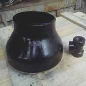
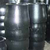
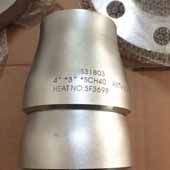
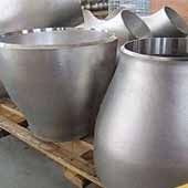
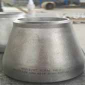
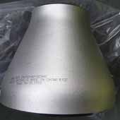
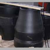
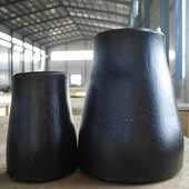
Pipe Fitings Chrome Alloy Steel Concentric Reducer According to the ASME B16.9 Concentric Reducer specification, the following materials can be used to manufacture reducers - , Hastelloy, Titanium, Monel, Nickel, Inconel Tantalum, Stainless Steel, Alloy Steel, Carbon Steel, Cupro-Nickel 90/10 as well as Cupro-Nickel 70/30. Our regular production schedules include Stainless Steel Concentric Reducer B16.9 of different dimensions like - Stainless Steel ASME / ASTM SA / A403 SA / A 774 WP-S, WP-W, WP-WX in different stainless steel grades such as 304, 304L, 316, 316L, 304/304L, 316/316L, DIN 1.4301, DIN1.4306, DIN 1.4401, DIN 1.4404
A chrome alloy 90° elbow is a type of pipe fitting specifically made from chromium alloy steel, designed to facilitate a directional change of the pipeline by a 90-degree bend while offering the enhanced properties of chrome alloys.

The specification for Asme B16 9 Concentric Reducers covers fittings of any producible wall thickness. According to the ASME B16.9 specification, we manufacture reducers of various thickness or schedules such as - Schedule 5S, , S20, S30, STD ,10S, 20S, S10, 40S, S40, S60, S80, S100, XS, 80S, S120, S140, S160, XXS and etc.
The Specification for ASME B16.9 is a standard that covers Factory Made Wrought Steel Buttwelding Fittings like the Concentric Reducer Fitting. This Standard covers parameters such as the overall dimensions, ratings, tolerances, testing, and markings for both wrought carbon as well as alloy steel factory-made buttwelding fittings. The size range of the Concentric Reducer En 10253 2 covered in this specification ranges between NPS ½ inch up to 48 inches. The size range for both seamless and welded Ansi B 16.9 Concentric Reducer is different. To specify, the size range for seamless Asme B16.9 Reducer Dimensions are up to 24 inches, whereas welded Asme B16 9 Eccentric Reducer Dimensions are available in the size range between 8 inches up to 36 inches.
| Specifications | ASME B16.9 Concentric Reducer |
|---|---|
| Concentric Reducer Pipe Fittings size | Seamless Butt Weld Fittings: 1/2" - 10" Welded Butt Weld Fittings: 1/2" - 48" |
| BW Concentric Reducer Dimensions | ASME/ANSI B16.9, ASME B16.28, MSS-SP-43, BS4504, BS4504, BS1560, BS10 |
| Flanged Concentric Reducer Thickness | SCH10, SCH20, SCH30, STD SCH40, SCH60, XS, SCH 80, SCH 100, SCH 120, SCH 140, SCH 160, XXS available with NACE MR 01-75 |
| Reducer Types | Seamless / ERW / Welded / Fabricated Pipe Fittings |
| Concentric Reducer Type B Type | DN15-DN1200 |
| Connection | Welding |
| Bending Radius | R=1D, 2D, 3D, 5D, 6D, 8D, 10D or Custom Pipe Fittings |
| Size Range | ½" NB to 24" NB in Sch 10s, 40s, 80s, 160s, XXS. (DN6~DN100) |
| BW Concentric Reducer Fittings | Angle : 22.5 deg, 30deg, 45 deg, 90 deg, 180 deg, 1.0D, 1.5D, 2.0D, 2.5D, 3D, 4D, 5D,
6D, 7D-40D. Standard: ASME B16.9, ASME B16.28, ASME B16.25, MSS SP-75 DIN2605 JISB2311 JISB2312 JISB2313, BS, GB, ISO |
| Manufacturing process | Push, Press, Forge, Cast, etc. |
| Reducer Fittings Test Certificates | EN 10204/3.1B Raw Materials Certificate 100% Radiography Test Report Third Party Inspection Report, etc |
| Origin & Mills | Japanese, Indian, USA, Korean, European, Ukraine, Russian |
| Key markets and industries for Concentric Reducer |
|
| Application |
|
| Material Test Certificates (MTC) as per EN 10204 3.1 and EN 10204 3.2, Test Certificates certifying NACE MR0103, NACE MR0175 | |




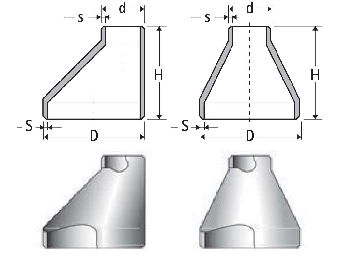
| Code RCD REISO | Ø BIG | Ø SMALL | HEIGHT H mm | THEORETICAL WEIGHT KG | ||||
|---|---|---|---|---|---|---|---|---|
| DN | D mm | Thickness S mm | DN | d mm | Thickness s mm | |||
| 27 21 | 3/4 | 26.9 | 2.3 | 1/2 | 21.3 | 2.0 | 38 | 0.08 |
| 33 21 | 1 | 33.7 | 2.6 | 1/2 | 21.3 | 2.0 | 50 | 0.09 |
| 33 27 | 3/4 | 26.9 | 2.3 | 0.09 | ||||
| 42 21 | 1"1/4 | 42.4 | 2.6 | 1/2 | 21.3 | 2.0 | 50 | 0.12 |
| 42 27 | 3/4 | 26.9 | 2.3 | 0.13 | ||||
| 42 33 | 1 | 33.7 | 2.6 | 0.14 | ||||
| *48 21 | 1"1/2 | 48.3 | 2.6 | 1/2 | 21.3 | 2.0 | 64 | 0.18 |
| 48 27 | 3/4 | 26.9 | 2.3 | 0.19 | ||||
| 48 33 | 1 | 33.7 | 2.6 | 0.20 | ||||
| 48 42 | 1"1/4 | 42.4 | 2.6 | 0.20 | ||||
| 60 27 | 2 | 60.3 | 2.9 | 3/4 | 26.9 | 2.3 | 76 | 0.30 |
| 60 33 | 1 | 33.7 | 2.6 | 0.31 | ||||
| 60 42 | 1"1/4 | 42.4 | 2.6 | 0.32 | ||||
| 60 48 | 1"1/2 | 48.3 | 2.6 | 0.33 | ||||
| 76 33 | 2"1/2 | 76.1 | 2.9 | 1 | 33.7 | 2.6 | 90 | 0.40 |
| 76 42 | 1"1/4 | 42.4 | 2.6 | 0.47 | ||||
| 76 48 | 1"1/2 | 48.3 | 2.6 | 0.48 | ||||
| 76 60 | 2 | 60.3 | 2.6 | 0.49 | ||||
| 89 42 | 3 | 88.9 | 3.2 | 1"1/4 | 42.4 | 2.6 | 90 | 0.55 |
| 89 48 | 1"1/2 | 48.3 | 2.6 | 0.61 | ||||
| 89 60 | 2 | 60.3 | 2.9 | 0.62 | ||||
| 89 76 | 2"1/2 | 76.1 | 2.9 | 0.63 | ||||
| 114 48 | 4 | 114.3 | 3.6 | 1"1/2 | 48.3 | 2.6 | 100 | 0.85 |
| 114 60 | 2 | 60.3 | 2.9 | 0.98 | ||||
| 114 76 | 2"1/2 | 76.1 | 2.9 | 1.00 | ||||
| 114 89 | 3 | 88.9 | 3.2 | 1.02 | ||||
| 139 60 | 5 | 139.7 | 4.0 | 2 | 60.3 | 2.9 | 127 | 1.60 |
| 139 76 | 2"1/2 | 76.1 | 2.9 | 1.70 | ||||
| 139 89 | 3 | 88.9 | 3.2 | 1.74 | ||||
| 139 114 | 4 | 114.3 | 3.6 | 1.76 | ||||
| *168 76 | 6 | 168.3 | 4.5 | 2"1/2 | 76.1 | 2.9 | 140 | 2.60 |
| 168 89 | 3 | 88.9 | 3.2 | 2.70 | ||||
| 168 114 | 4 | 114.3 | 3.6 | 2.82 | ||||
| 168 139 | 5 | 139.7 | 4.0 | 2.94 | ||||
| 219 114 | 8 | 219.1 | 6.3 | 4 | 114.3 | 3.6 | 152 | 5.03 |
| 219 139 | 5 | 139.7 | 4.0 | 5.12 | ||||
| 219 168 | 6 | 168.3 | 4.5 | 5.18 | ||||
| *273 114 | 10 | 273.0 | 6.3 | 4 | 114.3 | 3.6 | 178 | 7.00 |
| *273 139 | 5 | 139.7 | 4.0 | 7.20 | ||||
| 273 168 | 6 | 168.3 | 4.5 | 7.40 | ||||
| 273 219 | 8 | 219.1 | 6.3 | 7.55 | ||||
| 323 168 | 12 | 323.9 | 7.1 | 6 | 168.3 | 4.5 | 203 | 11.00 |
| 323 219 | 8 | 219.1 | 6.3 | 11.10 | ||||
| 323 273 | 10 | 273 | 6.3 | 11.20 | ||||
N.B. code RCD = concentric reducers - code REISO = excentric reducers
* Only concentric
| NPS | LBS | KG |
| 3/4-1/2 | 0.17 | 0.08 |
| 3/4-3/8 | 0.15 | 0.07 |
| 1-3/4 | 0.4 | 0.18 |
| 1-1/2 | 0.4 | 0.18 |
| 1.1/4-1 | 0.5 | 0.23 |
| 1.1/4-3/4 | 0.4 | 0.18 |
| 1.1/4-1/2 | 0.4 | 0.18 |
| 1.1/2-1.1/4 | 0.7 | 0.32 |
| 1.1/2-1 | 0.62 | 0.28 |
| 1.1/2-3/4 | 0.54 | 0.24 |
| 1.1/2-1/2 | 0.5 | 0.23 |
| 2-1.1/2 | 0.9 | 0.41 |
| 2-1.1/4 | 0.84 | 0.38 |
| 2-1 | 0.76 | 0.34 |
| 2-3/4 | 0.7 | 0.32 |
| 2.1/2-2 | 1.5 | 0.68 |
| 2.1/2-1.1/2 | 1.38 | 0.63 |
| 2.1/2-1.1/4 | 1.25 | 0.57 |
| 2.1/2-1 | 1.25 | 0.57 |
| 3-2.1/2 | 2 | 0.91 |
| 3-2 | 1.8 | 0.82 |
| 3-1.1/2 | 1.7 | 0.77 |
| 3-1.1/4 | 1.6 | 0.73 |
| 3.1/2-3 | 3.15 | 1.43 |
| 3.1/2-2.1/2 | 2.88 | 1.31 |
| 3.1/2-2 | 2.75 | 1.25 |
| 3.1/2-1.1/2 | 2.5 | 1.13 |
| 3.1/2-1.1/4 | 2.4 | 1.09 |
| 4-3.1/2 | 3.5 | 1.59 |
| 4-3 | 3.38 | 1.53 |
| 4-2.1/2 | 3.25 | 1.47 |
| 4-2 | 3 | 1.36 |
| 4-1.1/2 | 2.88 | 1.31 |
| 5-4 | 6 | 2.72 |
| 5-3.1/2 | 5.75 | 2.61 |
| 5-3 | 5.5 | 2.49 |
| 5-2.1/2 | 5.25 | 2.38 |
| 5-2 | 5 | 2.27 |
| 6-5 | 8.5 | 3.86 |
| 6-4 | 8.25 | 3.74 |
| 6-3.1/2 | 8.25 | 3.74 |
| 6-3 | 8 | 3.63 |
| 6-2.1/2 | 7.25 | 3.29 |
| 8-6 | 13.2 | 5.99 |
| 8-5 | 12 | 5.44 |
| 8-4 | 11 | 4.99 |
| 8-3.1/2 | 11 | 4.99 |
| 10-8 | 22 | 9.98 |
| 10-6 | 21.5 | 9.75 |
| 10-5 | 21 | 9.53 |
| 10-4 | 20 | 9.07 |
| 12-10 | 34 | 15.42 |
| 12-8 | 32 | 14.51 |
| 12-6 | 31 | 14.06 |
| 12-5 | 30 | 13.61 |
| 14-12 | 60 | 27.22 |
| 14-10 | 59.2 | 26.85 |
| 14-8 | 58.5 | 26.54 |
| 14-6 | 58 | 26.31 |
| 16-14 | 71 | 32.21 |
| 16-12 | 70 | 31.75 |
| 16-10 | 69.5 | 31.52 |
| 16-8 | 68.5 | 31.07 |
| 16-6 | - | - |
| 18-16 | 85 | 38.56 |
| 18-14 | 84 | 38.1 |
| 18-12 | 83 | 37.65 |
| 18-10 | 82 | 37.19 |
| 18-8 | - | - |
| 20-18 | 125 | 56.7 |
| 20-16 | 124 | 56.25 |
| 20-14 | 122 | 55.34 |
| 20-12 | 120 | 54.43 |
| 20-10 | - | - |
| 20-8 | - | - |
| 22-20 | 142 | 64.41 |
| 22-18 | 138 | 62.6 |
| 22-16 | 131 | 59.42 |
| 22-14 | 123 | 55.79 |
| 22-12 | - | - |
| 22-10 | - | - |
| 24-22 | - | - |
| 24-20 | 150 | 68.04 |
| 24-18 | 148 | 67.13 |
| 24-16 | 145 | 65.77 |
| 24-14 | - | - |
| 24-12 | - | - |
| 24-10 | - | - |
| 26-24 | 207 | 93.89 |
| 26-22 | 200 | 90.72 |
| 26-20 | 190 | 86.18 |
| 26-18 | 182 | 82.55 |
| 26-16 | - | - |
| 26-14 | - | - |
| 26-12 | - | - |
| 28-26 | 224 | 101.6 |
| 28-24 | 216 | 97.98 |
| 28-22 | 210 | 95.25 |
| 28-20 | 199 | 90.26 |
| 30-28 | 241 | 109.32 |
| 30-26 | 232 | 105.23 |
| 30-24 | 224 | 101.6 |
| 30-22 | 220 | 99.79 |
| 30-20 | 220 | 99.79 |
| NPS | LBS | KG |
| Nominal Pipe Size | 1/2 to 2.1/2 | 3 to 3.1/2 | 4 | 5 to 8 |
| Outside Diameter at Bevel (D) |
+ 1.6 – 0.8 |
1.6 | 1.6 | + 2.4 – 1.6 |
| Inside Diameter at End | 0.8 | 1.6 | 1.6 | 1.6 |
| Overall Length (H) | 2 | 2 | 2 | 2 |
| Nominal Pipe Size | 10 to 18 | 20 to 24 | 26 to 30 | 32 to 48 |
| Outside Diameter at Bevel (D) |
+ 4 – 3.2 |
+ 6.4 – 4.8 |
+ 6.4 – 4.8 |
+ 6.4 – 4.8 |
| Inside Diameter at End | 3.2 | 4.8 | + 6.4 – 4.8 |
+ 6.4 – 4.8 |
| Overall Length (H) | 2 | 2 | 5 | 5 |
| Wall Thickness (t) | Not less than 87.5% of Nominal Wall Thickness | |||